Early KW2000 Transceivers
EARLY KW2000 TRANSCEIVERS
Its quite difficult to trace the timeline of the early KW2000 radios, but as far as I can tell looking through the KW magazine adverts there were at least 4 distinct variants of the MK 1 as KW fiddled with the design ;
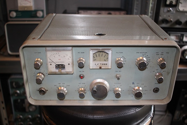
* The very first production run was quite short and ran from late 1963 until around May 1964. These models had the meter design from the prototype (used on the earlier boatanchor radios as well) and a very simple dial escutcheon (the prototype had no escutcheon). You can see that KW were clearly aiming at the emerging HF mobile market in this picture. These early variants are quite rare and I have not seen one for sale recently.
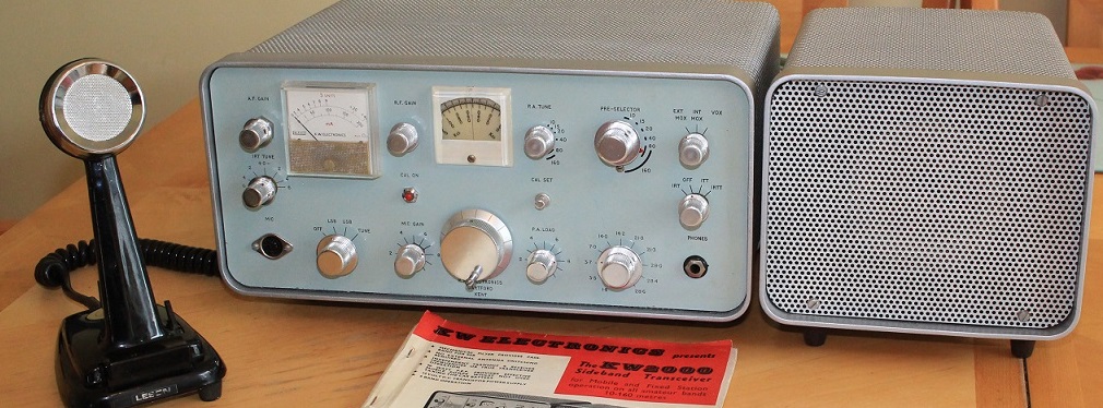
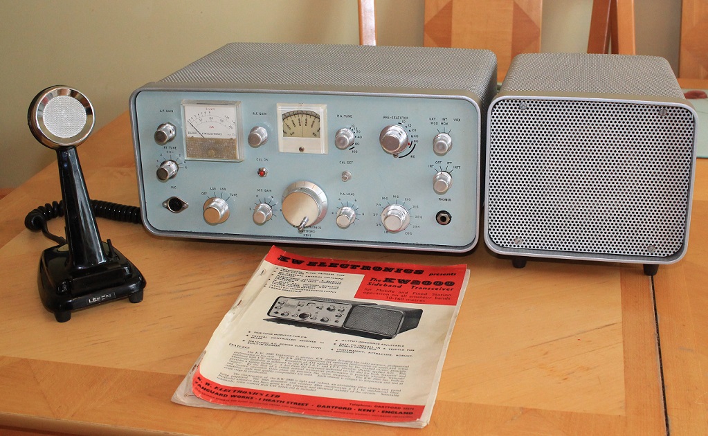
* The 2nd production run from May 1964 until Summer 1965. These models had the meter and escutcheon that was used on the later 2000A but were not in a 'G line' case and had the light blue front panel. The picture makes it appear as a slighly better looking home station ! I have 2 of these
* The final MK1 KW2000 production period ran alongside the 2000A in 1965/6 and had a small G line case (with the inspection lid and no mobile mounting bracket fixings). Early models of this period had the light blue front panel and later ones had the dark grey front panel (same as the 2000A). My friend Richard G3UGF believes there may have also been an option to buy a separate G Line case to improve the 'look' of the older models. I have one of these with the dark front panel and another in a G line case with a 'duck egg blue' front panel
The VFO dial on the 2000 / 2000A has a readout that just about manages a resolution of 2kHz and the odd (and unobtainable) slow motion drive has a tendency to wear so that you set a frequency and then the dial moves a little..called 'KW lumpy VFO syndrome'. There aren't enough 200kHz segments to cover 15m and 10m - another compromise. This link to a 1967 RSGB review of the 2000A on G4KFKs web pages reveals how poor the VFO drift can be - 45mins to stabilise and drifts 1.4kHz from cold. This would be laughable in the 21st Century !.
KW quickly added the 'separates' to the G line - the KW201 receiver and the 'Vespa' transmitter. Both of these were updated to become the KW202 RX and KW204 TX, but even into the 70's these lacked basic 'transceive' capability and had to be netted onto the same frequency. The KW 1000 linear amplifiers and antenna tuners have endured and many are still working in ham shacks to this day.
MID PERIOD MODEL KW2000 - MAY 2019
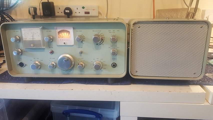
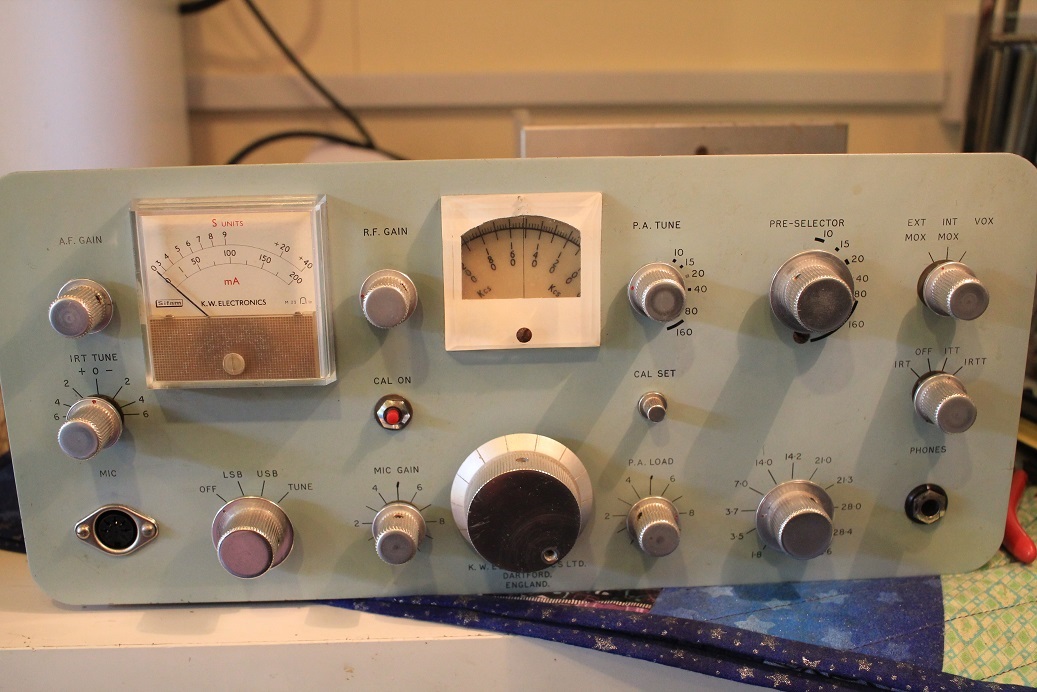
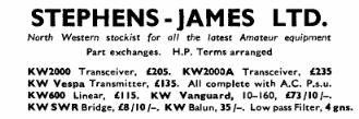
This KW2000 came from the Dunstable Downs rally - I just couldn't leave it there looking lonely and unloved. Pretty shabby with wrong meter front, wrong mic socket, no feet, modified KW power supply and very dirty. A key factor for me is that the front panel is almost unmarked with no extra holes and would look great cleaned up. Its a mid period one before KW moved to the darker front panel (1965/66) and grey case - serial number 319 (only 6 away from one my other early 2000s). On this one the case of both the rig and the PSU are light blue..it all matches. My web searches reveal the even at Serial No 459 there were light fronted KW2000s in G line cases..my one seems a very early S/N to have a G line case. Perhaps an early owner upgraded the case a year or 2 into its life...or maybe not!
I have done this sooo many times!! - off with all the knobs, remove front panel, clean relays, check key physical wiring and components. The case and bezel cleaned up very well and I wont repaint them -a previous owner may have been a smoker. Luckily I had a spare KW meter and period correct DIN mic socket.
As with almost all of my vintage radio purchases this one had been modded in a number of areas..notably the IRT range and as I soon found out - the VFO and Het Osc Valve heater wring. All the Hunts caps had gone and quite a few resistors had been changed..not the best soldering either. Mr Bodger has smeared some locking paint in a lot of the ferrite cores and may have broken some..so any proper alignment may be problematic...I have seen some awful work inside radios over the years
After 3 days work I put the front panel back on, checked the HT rail for any shorts, disconnected the PA Anode supply and applied power from a known good PSU. Thats when I spotted that a past owner had rewired the VFO and Het Osc valves to run from 6V rather than 12V ( later 2000A/B/E models ran these 2 valves at 6V). Running these valves from a separate LV supply brought the RX to life...and the filter still works.
Dismantling the PSU showed that a 6V regulator had been added (badly) to run these 2 valves - our bodger used the correct spare pin on the multiway power cable to do it. The two valves run from this regulator seemed a bit bright..when I checked the voltage they were running at 6.9V !. I decided to remove this 6.9v regulated supply and put in the LM309 version used in the 2000E, this adds 2 diodes in the ground leg of the 5v regulator to get an accurate 6.4v -much better. The nasty 15 way Plessey power connector from the PSU also broke and to be safe I put my one brand new spare on.
One transformer had been changed for a larger one and this meant a previous owner bodged the location of the speaker so it all fitted in. Before checking for TX I measured the resistance of the 700V anode supply to the single 6146 to ground...it was a dead short !. For some reason Mr Bodger had to change the ceramic EHT decoupling capacitors near the anode choke.
There should be 2 Disc ceramics in parallel but he put in an old grey RS tubular capacitor - it was unsuitable for RF decoupling and had failed to a short circuit. 2KV disc ceramics restored order. 80 and 40 immediately produced 60W PEP with lots of drive - in fact too much drive! I worked out what Mr Bodger had done before I even checked the rig wiring - he got much more mic gain by adding the VOX amplifier triode into the mic circuit, only one wire needed to be moved. It was too much and the TX audio was distorted, I put it back to stock. I then discovered that yet again a stupid past owner couldn't tell the differerence between 470K and 47K and put the wrong value resistor on the grid of the cathode follower driving the balanced modulator - no wonder he needed more mic gain..what a grade 1 idiot. Pic below is the working radio after 5 days work..new speaker grill required, Mr Bodger just had to drill holes in the middle of it !
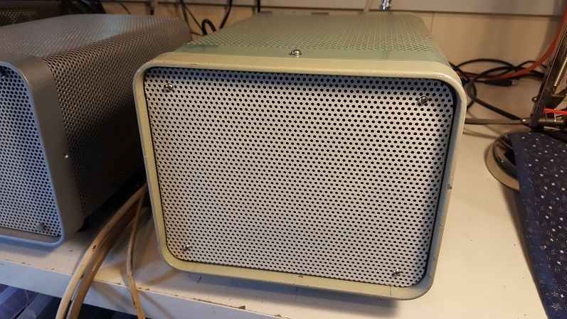
Thanks goodness for eBay...just a few £ for piece of perforated aluminium - bent up using the original grill as a template the PSU looks far better. Made a new speaker baffle from scrap wood (the original must have been lost). As the PSU is non standard I still needed some screws in the front, but painted 'off white' it looks great. I may leave the bezel and case paint untouched on this rare colour example
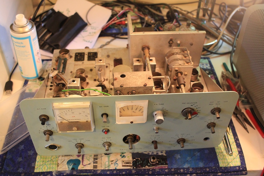
BELOW - After nearly 3 weeks work, there is not much more I can do. The dial escutcheon has been replaced with a white paper printout cut to size. As the radio works well on most bands I have only carried out minimal re-alignment.
LATE MODEL 'G LINE' 1966/7 KW 2000 - FEBRUARY 2018
Took delivery of these exceptionally clean 1966/7 2000 MK1 (and another PEP METER) after seeing an advert on Gumtree (London). The radio had not been bodged in any way and was even partly tested by the seller using a GDO on RX. When I spoke to him he was convinced it was up to 6MHz off frequency. I was not so sure unless all the heterodyne crystal had been mixed up, which would be very odd for an unmolested radio..after all old GDOs can be wildy inaccurate, or perhaps he was reading from the wrong scale.
Before I ran it on my own PSU I spotted a few of the nasty black Hunts caps..I changed all of them and the normal resistors that go high, although I was surprised to see some resistors already changed. The PA 6146 looked a bit sad so I put a NOS 6146 in to be on the safe side

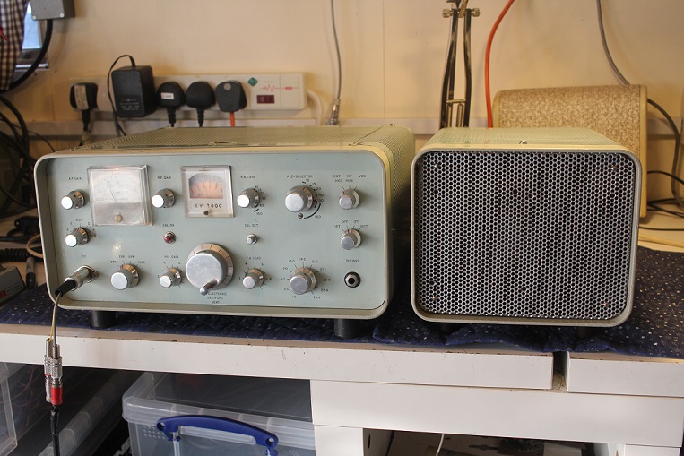
After cleaning the switches and pots it came up straight away with no issues (and spot on frequency). The TX on 80m gets great reports and I can get over 60W peak out of it easily. Cosmetically it was also in great condition and a quick clean of the case showed no real need for a repaint..its super clean
EARLY MODEL 'PRE G LINE' KW2000 (X 2 !) MAY 2017
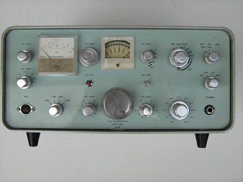
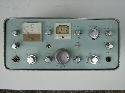
Took delivery of 2 early 2000s in May 2017. The serial numbers are close (299 and 313), probably 1964 vintage. Came from the same eBay purchase complete with Power Supplies. One of these radios (on the left) had been stripped down and partially restored, the other had some new parts fitted but very shabby. The'Pre G line' cases are very thin and poor quality, you can see why KW moved up to the better quality cases.
 There
was a big difference in the state of these two radios, the one on the
left had been very well cleaned up - someone had worked hard on it. With
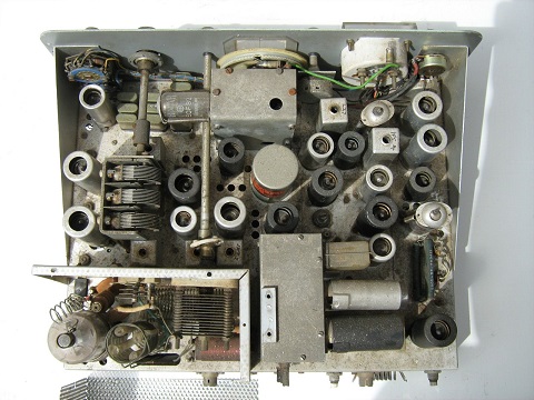
the unrestored KW2000 (right) I started to encounter some new
issues...for some reason the ferrite slugs in some of the coils had been
exposed to damp and had jammed rigid - what ever I tried (oil, wd40 ete
etc) I could not move some of them. If was ever going to align the radio
properly after restoration I had to do something. The only option was to
remove the coils and very carefully try and chip the core out. I
ended up using a drill and a 6mm tap and took it very easy so that the
formers were not damaged. the worst was one of the broad band coupler
coils with has 2 slugs. This radio also had a lot of component changes
and not all of them the correct value..ARGHHHHH, the bodgers..why dont
they get it right or leave it alone?. At least he didn't use an electric
drill on it! . The radio was extremely dirty with quite a few dry
joints, wiggle a suspect component and it comes off in your hand. Surely
no one used it with the very odd parasitc choke?.its just a coil of
wire. As with my other projects I removed the valves, crystal, relays,
vox, PA and the front panel so I could clean both radios up. These are
just some of the issues I have faced fixing KW2000s..
There
was a big difference in the state of these two radios, the one on the
left had been very well cleaned up - someone had worked hard on it. With
the unrestored KW2000 (right) I started to encounter some new
issues...for some reason the ferrite slugs in some of the coils had been
exposed to damp and had jammed rigid - what ever I tried (oil, wd40 ete
etc) I could not move some of them. If was ever going to align the radio
properly after restoration I had to do something. The only option was to
remove the coils and very carefully try and chip the core out. I
ended up using a drill and a 6mm tap and took it very easy so that the
formers were not damaged. the worst was one of the broad band coupler
coils with has 2 slugs. This radio also had a lot of component changes
and not all of them the correct value..ARGHHHHH, the bodgers..why dont
they get it right or leave it alone?. At least he didn't use an electric
drill on it! . The radio was extremely dirty with quite a few dry
joints, wiggle a suspect component and it comes off in your hand. Surely
no one used it with the very odd parasitc choke?.its just a coil of
wire. As with my other projects I removed the valves, crystal, relays,
vox, PA and the front panel so I could clean both radios up. These are
just some of the issues I have faced fixing KW2000s..
-
Wrong value or out of spec resistors on the screen grids and anodes of the RX RF amp and IF amps. Check all cathode resistors. Only a few electrolytics in the actual radio and only one on the HT
-
ALL HUNTS black axial capacitors must go. No matter what you think about the radios performance, they are truly awful. They were identified as a problem in TV and Radio sets as far back as the 60's with some estimating a design life of only 5 years If you find them, they must ALL be replaced. The ones near the balanced modulator are hard to get at but will sap your audio drive if you dont bite the bullet and change them !! They are mainly present in earlier KW gear.
-
The rubber band holding ferrite slugs in the coils can turn to cement - they will never turn again. First time I have seen this.
-
Broken central spigot on the 6146 final in one radio..and yes, I did plug it back in wrong as I hadn't noticed..lucky there was no bang, it just upset the heater balance
-
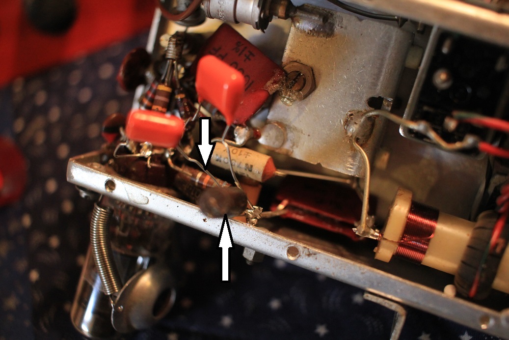
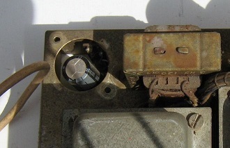
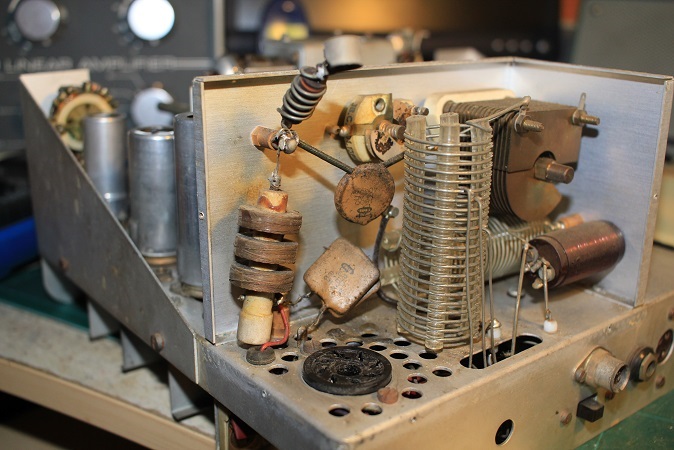
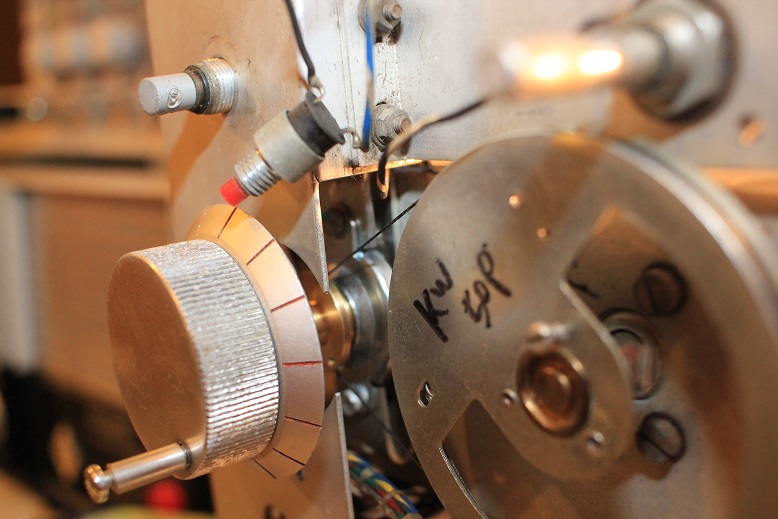
 VFO
faults - low output or only oscillates at the bottom of the
band..if the resistors checkout OK (you can test a lot of them with
the valve out and measure resistance between the valveholder and the
150v HT or ground), it may be nasty HUNTS bypass caps
inside the VFO. I test the units with 6.3v and 150v on an external
power supply and a scope. The difference in output with new caps is
staggering. The VFO has to come out though ! This pic shows the
location of the caps (one
is hidden behind the resistor)...I have snipped the leads to tack on
2 new caps and check the VFO operation before the final fix.
VFO
faults - low output or only oscillates at the bottom of the
band..if the resistors checkout OK (you can test a lot of them with
the valve out and measure resistance between the valveholder and the
150v HT or ground), it may be nasty HUNTS bypass caps
inside the VFO. I test the units with 6.3v and 150v on an external
power supply and a scope. The difference in output with new caps is
staggering. The VFO has to come out though ! This pic shows the
location of the caps (one
is hidden behind the resistor)...I have snipped the leads to tack on
2 new caps and check the VFO operation before the final fix. -
My NOS resistors may only last 30mins before failing.
-
Mr Bodger doesn't know a 47K resistor from a 470K resistor.....always trying to catch me out !
-
RF choke in the cathode of the 2nd TX mixer OC ...now I know why I had no power out. Also checked the RF Chokes in the Driver stages, often burnt but still sort of working. Replace
-
Always replace the PA grid coupling cap and check all PA components for signs of stress
-
More dry joints than I had seen in a while (in both of them). This was mainly due to botched component changes and mods rather than KW assembly faults...and the odd Hunts black capacitors that had been left were changed.
-
The strange purple wire in the wiring loom near the Mic socket of Mk1 2000s...doesn't go anywhere..checked the other radios..same wire just with a bit of sleeving over the end...odd
-
Very poor carrier suppression - more HUNTS capacitors, leaky diodes (only 2 of them) can be replaced with modern BAT85. One of the 453 or 457kHz carrier cystals has drifted into the filter passband or vice versa!.
-
Strange AGC performance will probabaly be due to poor / leaky RX IF amp valves (both 6BA6), or the EF183 RF amplifier.
-
The PA driver 6CH6 can take off without its screening can...same as Heathkits !
-
The rear 2 bandswitch sections wear and mean the PA coil taps may not connect reliably. Its not so much the contacts, the rotor part is worn where the shaft goes through..I think replacement is the only solution - but difficult
-
Complete realignment (premix crystal oscillator is often way out on a least one band), and dont forget that nail varnish remover to soften the glue on many of the coils wound directly on the ferrite slugs..you will never ever align the radio properly without it !...the premix crystal osc drive is critical for the TX, you wont notice it as much on receive. Put a scope on the EF91 crystal osc output and tune each band for maximum
-
The mechanical filters can still work after 53 years!

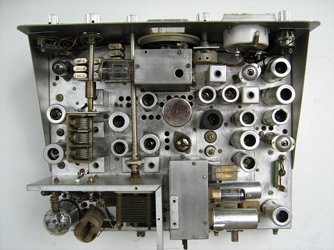
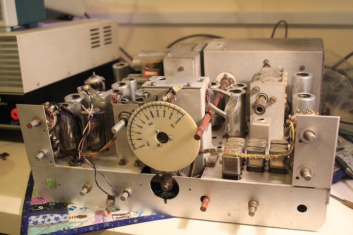
STRIP DOWN PICTURES, FRONT PANEL BACK ON, CRYSTALS POLISHED !
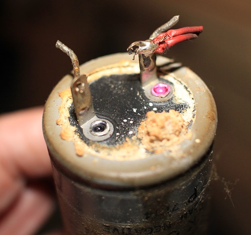
OH DEAR ! ANOTHER BODGE NEW CAPS SLEEVED TO FIT PSU
 After an extensive strip down, deep clean
and renovation both Mk1 radios are working well on the low bands. The
PSUs also got a complete refurbishment, I replaced all the capacitors,
resistors and associated components - the left and middle pics above
show how bad things had got and how Mr Bodger fixed it (no capacitor
mounting bracket). I replace all capacitors with modern small
components, but make up proper fixing hardware (right). I reconditioned
the paper cone loudspeakers and baffles and replaced all the tarnished
screws (including new cabinet feet).
My research on the case colour of these early radios threw up some odd results - very early
models may have had a darkish blue case, although it appeared this
quickly changed to a light hammered grey. The bezel is part of the case
and cant be easily removed (although on one of mine the rivets had been
drilled out of the PSU bezel so it could removed). I rubbed down
and test sprayed one of the cases with hammerite smooth silver which gave very
pleasing results and was close to the original colour. Click on the pic
above for a larger image of this fantastic restored radio. The
microphone is a c1970 rebadged 'Turner + 2 CB/ Ham power mic', all metal
made in japan and picked up at a rally for £10 - works fine.
After an extensive strip down, deep clean
and renovation both Mk1 radios are working well on the low bands. The
PSUs also got a complete refurbishment, I replaced all the capacitors,
resistors and associated components - the left and middle pics above
show how bad things had got and how Mr Bodger fixed it (no capacitor
mounting bracket). I replace all capacitors with modern small
components, but make up proper fixing hardware (right). I reconditioned
the paper cone loudspeakers and baffles and replaced all the tarnished
screws (including new cabinet feet).
My research on the case colour of these early radios threw up some odd results - very early
models may have had a darkish blue case, although it appeared this
quickly changed to a light hammered grey. The bezel is part of the case
and cant be easily removed (although on one of mine the rivets had been
drilled out of the PSU bezel so it could removed). I rubbed down
and test sprayed one of the cases with hammerite smooth silver which gave very
pleasing results and was close to the original colour. Click on the pic
above for a larger image of this fantastic restored radio. The
microphone is a c1970 rebadged 'Turner + 2 CB/ Ham power mic', all metal
made in japan and picked up at a rally for £10 - works fine.
 MISSING
C19 CAPACITOR IN EARLY KW2000 MODELS
MISSING
C19 CAPACITOR IN EARLY KW2000 MODELS
In the course of restoring KW2000MK1s and early KW2000A I discovered a little undocumented KW mod. ALC wasn't fitted until 1967 on the later 2000A models and without it there was danger of splatter if the mic gain was set to high. KW must have decided to cut the drive down a bit by removing the cathode bypass .01 cap (C19) in the TX Amplifier (V3) but never took it off the schematic. When I first discovered it I blindly put the cap back (thinking Mr Ham Radio Bodger had removed it)..and immediately had more drive...and splatter. So far 3 of my early radios have this cap missing. Good old KW trying to catch me out !
LATE MODEL MK1 KW2000 - MARCH 2017
This scruffy and rather shabby later
period Mk1 looked very sad on
first inspection. It is period correct with a single 6146 PA, in the
small chassis, better 'G line' case and with the strange VOX BOX. This odd box
is shoe horned into all the early 2000s on a large multiway connector in
what looks like a real bodge job. Oddly there is an unused valve holder
hole in the chassis under the VOX BOX of these radios - so it looks as
if some last minute design changes were made!. Although KW called it an option the
radio won't go into transmit without this unit. I think its a pity that
they had this extra unit fitted , the prototype 2000 didn't appear to
have it and looked very nice
 indeed.
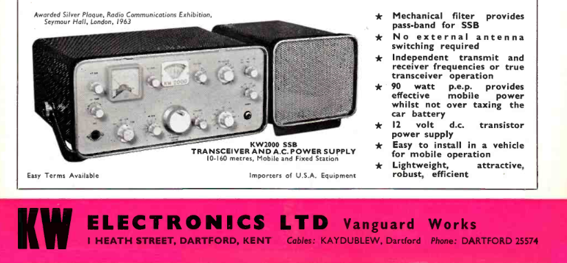
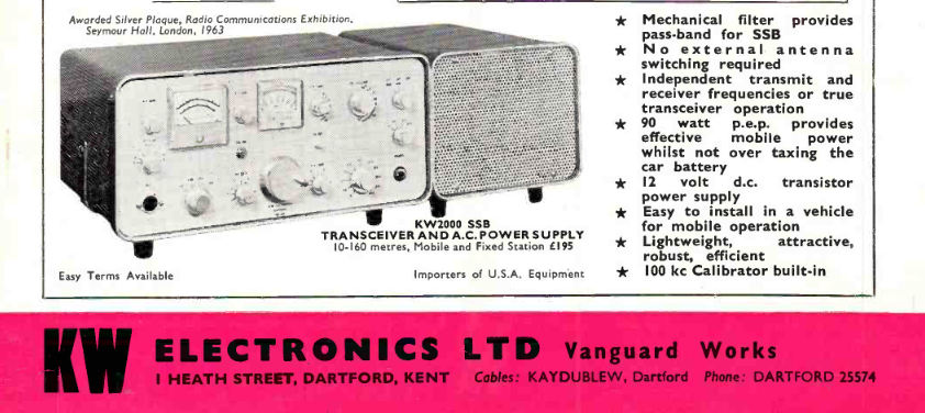
The MK1 2000 had an odd production run from late 1963. By December 1964
KW was advertising the improved KW2000A model but continued to market
the MK1 until the end of 1966
(advert on left from August 1966) . The only explanation I can come up with is that KW stuck with the MK1 as its
smaller size and lower output power made it
better suited to mobile operators. It was not in any KW adverts by the
start of 1967. This example is from the later period of production as the
front panel is the darker colour of a 2000A
indeed.
The MK1 2000 had an odd production run from late 1963. By December 1964
KW was advertising the improved KW2000A model but continued to market
the MK1 until the end of 1966
(advert on left from August 1966) . The only explanation I can come up with is that KW stuck with the MK1 as its
smaller size and lower output power made it
better suited to mobile operators. It was not in any KW adverts by the
start of 1967. This example is from the later period of production as the
front panel is the darker colour of a 2000A
This 2000 came from a museum that had closed - it was bought untested for display and had not been used since sometime well before 1993.
I left the very dirty PSU to one side and checked the radio first. A thorough and deep clean normally reveals the the first few problems. Nothing for it but to remove the front panel, the vox box, all the valves, relays, PA cover and get to work with soapy water and a stiff brush (not quite the soaking that some Collins and Heathkit restorers advocate). The aluminium knobs are particularly hard to clean up but can be brought back to reasonable condition. As expected some issues soon came to light. The PA Anode RF choke had been replaced - badly, the 6146 looked in poor health, the VFO slow motion drive had failed and a different Jackson one had been grafted on. The case was also partly repainted (?) in the wrong colours..radio ham bodgers should be kept well away from spray paint!.
I changed the components that normally give problems (screen and anode resistors / bypass capacitors), plugged it in to a spare KW PSU and it came to life !. After a touch of alignment and a rebuild of the PA I dared to transmit..and after a little bit of adjustment we had good power out on 160, 80 and 40m. It drifts less than my 3 other KW2000s and by all accounts sounds fine on 80 and 40m, and how did the mechanical filter manage to last over 50 years?.
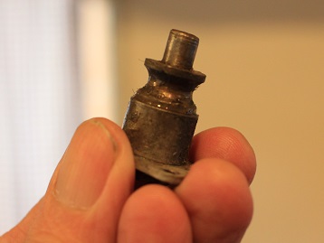 The 2000, 2000A and Vespa used a strange
Jackson (?) slow mo drive and a dial cord to turn the VFO. - these
drives are unobtainable in the 21st Century. Although Jackson drives are
available again, to the best of my knowledge this type has not been
remade with the precise dimensions to drop straight in. What's odd about
it is that its just a concentric drive, the pulley sleeve is the output..there is
no shaft at the rear. The most common failure mode is that the ball bearings
fail of break up and the central shaft is often jammed. The
VFO still tunes but really quickly !. I had to find a solution and had a
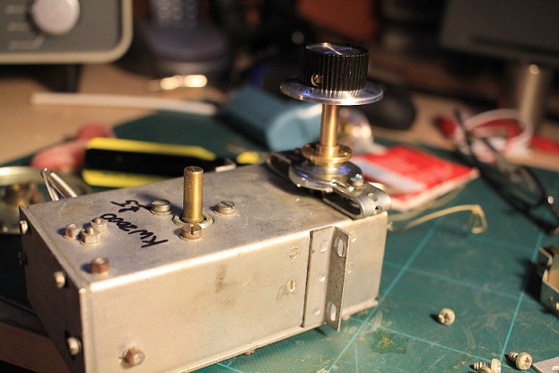
spare 2000 VFO to practice on - I found I could use a new Jackson
4511DAF drive (as used on the 2000B) with some
small homemade aluminium brackets. It was fiddly to make them and
I spent a few hours with the needle files until I was sure it would
work. When I make another set for my Vespa drive I will make them a
fraction smaller..live and learn.
The 2000, 2000A and Vespa used a strange
Jackson (?) slow mo drive and a dial cord to turn the VFO. - these
drives are unobtainable in the 21st Century. Although Jackson drives are
available again, to the best of my knowledge this type has not been
remade with the precise dimensions to drop straight in. What's odd about
it is that its just a concentric drive, the pulley sleeve is the output..there is
no shaft at the rear. The most common failure mode is that the ball bearings
fail of break up and the central shaft is often jammed. The
VFO still tunes but really quickly !. I had to find a solution and had a
spare 2000 VFO to practice on - I found I could use a new Jackson
4511DAF drive (as used on the 2000B) with some
small homemade aluminium brackets. It was fiddly to make them and
I spent a few hours with the needle files until I was sure it would
work. When I make another set for my Vespa drive I will make them a
fraction smaller..live and learn.
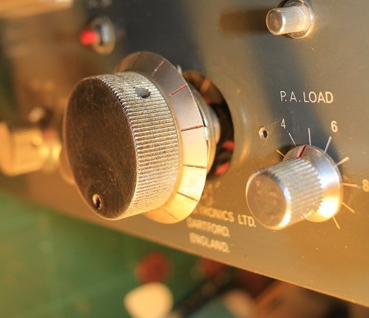
The dial cord only has a light load and works fine on the outer part of modern drive. I did not have to make any mechanical changes to the radio or the VFO to do the work..so the mod can reversed if another drive turns up. A previous owner had already drilled extra holes in the front panel, my mod didn't need them -radio ham bodgers should be kept away from electric drills !. Once released from the main chassis the VFO and drive can be removed as one complete unit. The hardest part was measuring and getting the dial cord on. I came up up with a work around for that as well - I pretensioned the dial cord spring with a thin pice of wire and got the dial cord as tight as I could, then with it all assembled I cut the wire holding the spring and it pulled the cord very tight..needs must. If you look carefully at the pics you can see the two little holes I drilled in the big VFO pulley to hold my wire tensioner..neat !!
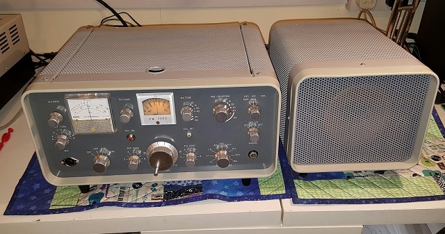
The finished radio looks brand new - case repainted in 'Ford Polar Grey', bezel repainted in 'Ford Dove Grey' and the new slow motion drive now looks and works as it should. I re-capped the Power Supply (which did have Hunts capacitors fitted), I just dont trust 50 year old electrolytic caps. That also came up OK and after a repaint the pair look absolutely fantastic. In 2018 I changed the mechanical filter (which had quite a high loss of at least 20dB) - my quick fix was to use a filter fitted with a Murata CFJ455K. This is a bit wider and the overall shape is not quite as good but it has restored TX and RX gain. I'll have the old one apart in the near future
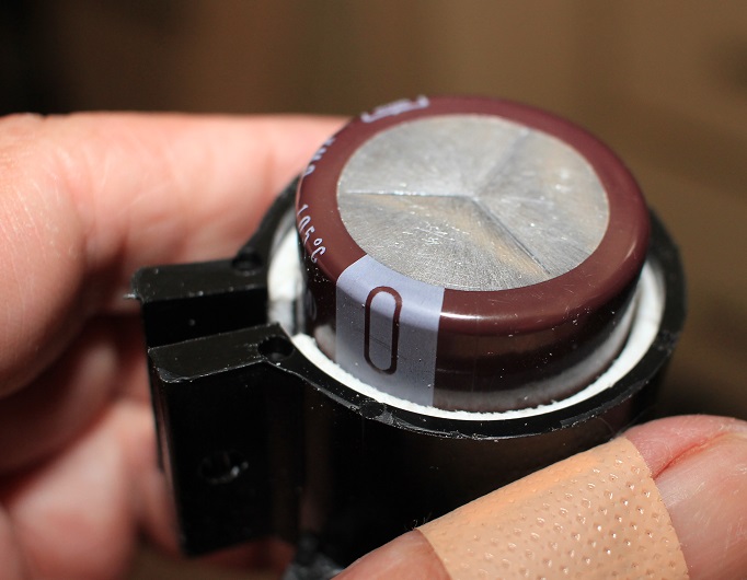
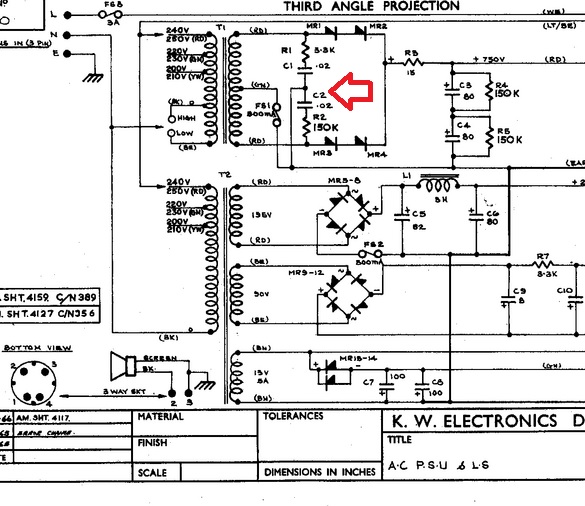
Early KW2000 PSU
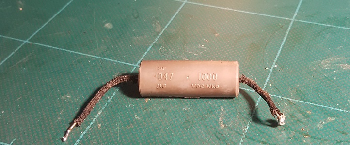
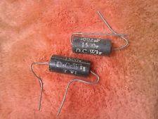
Some of the early KW2000 power supplies had 'snubber' capacitors across the AC EHT winding of the transformer (there are 2 transformers in these supplies). The .02 capacitors are rated at 800v and have a series resistor. If they are present they will probably be the grey tube type marked up with the RS (Radios Spares), ' running man' logo. I have had 2 catastrophic failures of these components and feel that they should be either removed or changed as part of a refurbishment. In KW gear I now change the EHT diodes for modern ones and remove these capacitors all together.
Connect with me today
Call me on 44 (0)7970 190437