 KW1000,
SWR Meters, Tuners, KW2000CAT
KW1000,
SWR Meters, Tuners, KW2000CAT
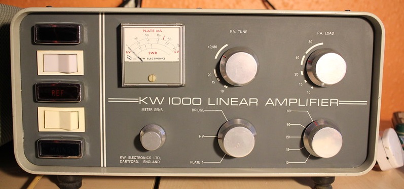
APRIL 2016 - KW 1000 LINEAR AMPLFIER
With the next
 KW
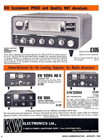
purchase it dawned on me that I had collected every item in this 1968
advert from the RSGB RadCom magazine from 1968. The prices were quite
revealing as well - I had paid less in 2016 for each item than the 1968
price. The only trivial difference was that my KW Vespa was a Mk1 and
not a Mk2 model (that had a sweep tube PA). The KW1000 was another
stunning eBay purchase from ham about 60 miles away. The amplifier is in
A1 cosmetic condition - which is very rare for any equipment over 40
years old. In true KW tradition the mechanical construction can best be
describes as agricultural. There are no EHT interlocks and once removed from
the case there is no cover over the PSU and the HV capacitors are facing
upwards...so not a place to put your fingers. All the panels are held
together with different screws, but at least its rugged!.
KW
purchase it dawned on me that I had collected every item in this 1968
advert from the RSGB RadCom magazine from 1968. The prices were quite
revealing as well - I had paid less in 2016 for each item than the 1968
price. The only trivial difference was that my KW Vespa was a Mk1 and
not a Mk2 model (that had a sweep tube PA). The KW1000 was another
stunning eBay purchase from ham about 60 miles away. The amplifier is in
A1 cosmetic condition - which is very rare for any equipment over 40
years old. In true KW tradition the mechanical construction can best be
describes as agricultural. There are no EHT interlocks and once removed from
the case there is no cover over the PSU and the HV capacitors are facing
upwards...so not a place to put your fingers. All the panels are held
together with different screws, but at least its rugged!.
Initial physical checks revealed a number of things that would need attention. The most obvious was the that the anode RF choke was burnt in the very middle, this a classic symptom of a resonance that has resulted in severe RF heating in the choke. After chatting with other owners of this linear it looks as if either a different choke was fitted at the factory or it was changed at some point, the output RF choke was also missing and not knowing why I decided to change the HV 'doorknob' capacitor as well. All the HV caps tested OK although the balancing resistors are quite low value at 25K..so quite a bit of heat.
I'll make up a PCB with modern caps and higher resistors at some point. My next mod before switch on was to insert an 800mA fuse in the EHT in series with a 10R 'glitch' resistor to limit the current should there be a tube flashover. I wound 2 different anode RF chokes - the first was close to the Heathkit SB200 design of 50 - 60uH, this worked OK but I was concerned that the inductance was too low for 80m and there could be RF on the EHT smoothing caps (despite extensive decoupling), in the end I went with a value over 120uH and a winding gap in the middle. I couldn't tell much difference but the engineer in me feels better !
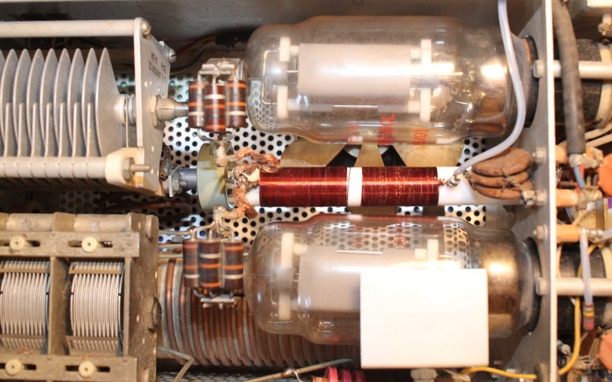
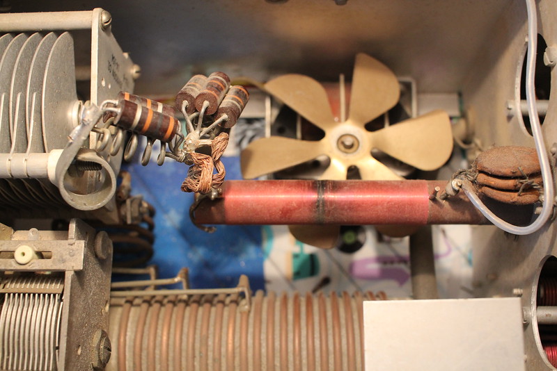
Pictures of new choke and the burnt one on the right. Good power out on 40 and 80 from the Chinese 572b tubes already in the amplifier...over 500W out when driven from my KW2000A
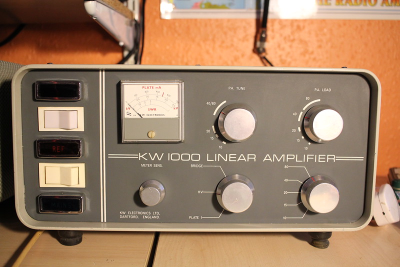
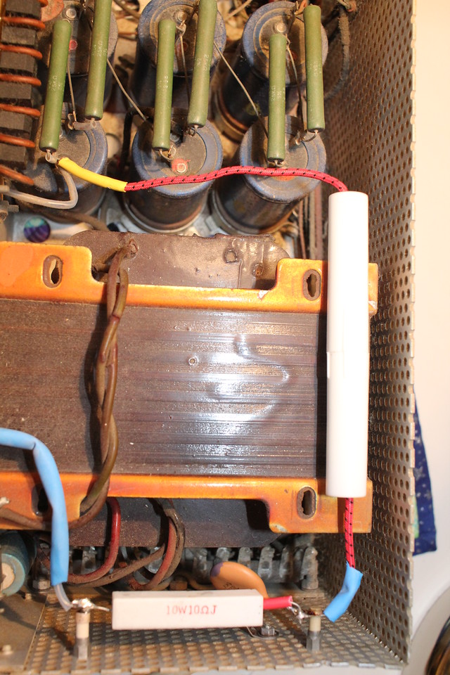 This Pic of the KW1000 linear shows the plastic sleeved 800mA
microwave oven fast blow fuse, I have also added a high power 10R
'glitch' resistor to limit the current should the tubes ever flash
over..not a problem years ago but Chinese 572 tubes are notorious
for variable quality and cannot really be trusted. Those 25K
balancing resistors sure do get hot..modern caps and higher value
resistors to add soon
This Pic of the KW1000 linear shows the plastic sleeved 800mA
microwave oven fast blow fuse, I have also added a high power 10R
'glitch' resistor to limit the current should the tubes ever flash
over..not a problem years ago but Chinese 572 tubes are notorious
for variable quality and cannot really be trusted. Those 25K
balancing resistors sure do get hot..modern caps and higher value
resistors to add soon
TUNERS AND POWER METERS
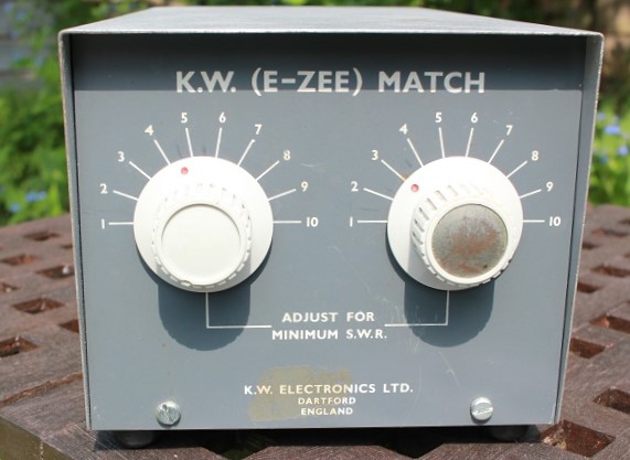
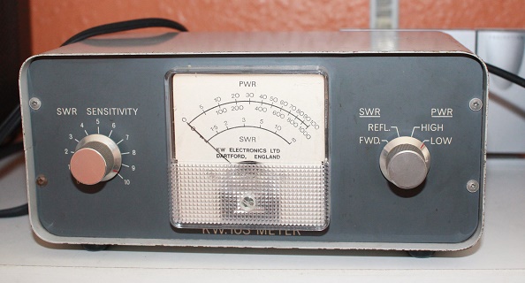
Loads of Hams in my early years bought a KW'EZEE' Match, it was the only easily available balanced tuner without a lossy balun. Power handling was bit limited, 100 - 200 W at the most. It could arc over in some matching situations with too much power. Still sought after - although some just ask too much money for them. KW103 Power / SWR meter has been in my possession since the 70's. KW did put the match and the meter into one box (KW107/9), but people ask silly money for them (more than I have paid for a complete transceiver in some cases). After bartering unsuccessfully with a trader for a repainted KW101 SWR meter (he wanted £20 I offered £15) at the Eastbourne Rally in 2016 - he told me 'its KW mate and collectable'. Funny thing is one went on eBay for £10 a few days before, I gave up and walked away..same rally £20 for a kokusai filter, trader would not take £10. I paid less on eBay
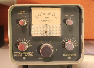 Rare
KW105 - Bought from a friend in 2017 the 105 does not appear to
have been made for very long in the early 70's and was quickly
superceded by the 107 and the higher power handling 109. Its still and
'EZEE Match' inside with unbalanced connections for the 80 - 10m bands
on 5 separate sockets, and the two sets of balanced connectors which are
not switched and must not be used at the same time as the unbalanced
ones. The 105 switch positions are not marked on the front and this must
have been confusing as they are marked on the back !. There is no
'through' position meaning its in circuit all the time and the SWR meter
is not calibrated as a power meter as it is on the later models. Its
super clean unlike many of the expensive 107s I see at rallies in the
UK.
Rare
KW105 - Bought from a friend in 2017 the 105 does not appear to
have been made for very long in the early 70's and was quickly
superceded by the 107 and the higher power handling 109. Its still and
'EZEE Match' inside with unbalanced connections for the 80 - 10m bands
on 5 separate sockets, and the two sets of balanced connectors which are
not switched and must not be used at the same time as the unbalanced
ones. The 105 switch positions are not marked on the front and this must
have been confusing as they are marked on the back !. There is no
'through' position meaning its in circuit all the time and the SWR meter
is not calibrated as a power meter as it is on the later models. Its
super clean unlike many of the expensive 107s I see at rallies in the
UK.
Rare KW PEPMETER

Another oddity - I have not seen many of these. Although I think it can be used as standard 300W power meter (with a bandswitch), its primary purpose is to measure the transmit PEP int a dummy load. To do this the the operator must first connect the battery powered two tone audio signl into the transmitter MIC input. The TX is then loaded in the normal way and a calculation has to take place to give the user the PEP reading..100W PEP will read on the meter as 40.5W and 400W PEP will read 160W. Although its probably far better than many of the PEAK reading watt meters avaliable today, I'm not sure it ever caught on.
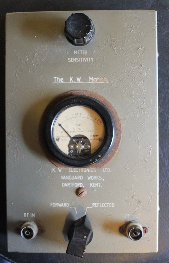 KW
'Match' SWR Bridge from the late 50's. Picked this up at Rally in August
2017, appears to work fine and is really more of a curiosity than
something I would use with my other KW gear. The 'form factor' is a bit
odd as well - it has to be laid flat rather than the front facing shape
that KW and most other manufacturers ended up with later. KW loved those
Belling Lee TV coax connectors that will be familiar to almost all older
UK hams !
KW
'Match' SWR Bridge from the late 50's. Picked this up at Rally in August
2017, appears to work fine and is really more of a curiosity than
something I would use with my other KW gear. The 'form factor' is a bit
odd as well - it has to be laid flat rather than the front facing shape
that KW and most other manufacturers ended up with later. KW loved those
Belling Lee TV coax connectors that will be familiar to almost all older
UK hams !
January 2018 JUNK SALE KW2000CAT
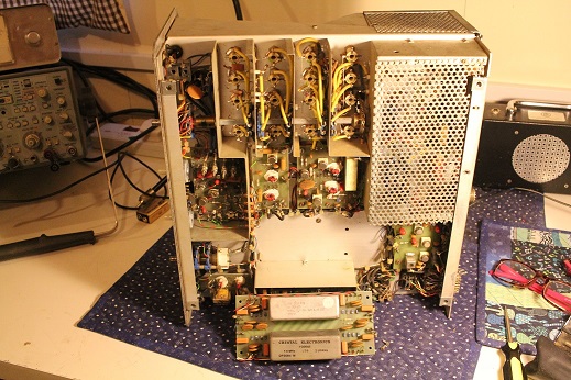
I was given this late model KW2000CAT 'HF Radio Telephone' by one of my ham chums who bought the chassis (no case!) for £1 at a surplus sale. On first inspection many of the important parts had been robbed out of it. The 1.4MHz ssb IF filters, the 1.4MHz carrier crystal and almost all the PA components have gone. I have located IF filters (after realising that KW use them in reverse - USB Filter for LSB operation etc). I may divide 14MHz by 10 to get the carrier osc, and the radio is single conversion - so I may be able to use one of my DDS oscillators on the LO input and get it going on receive..or maybe thats a step to far for a very sorry radio.
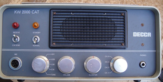
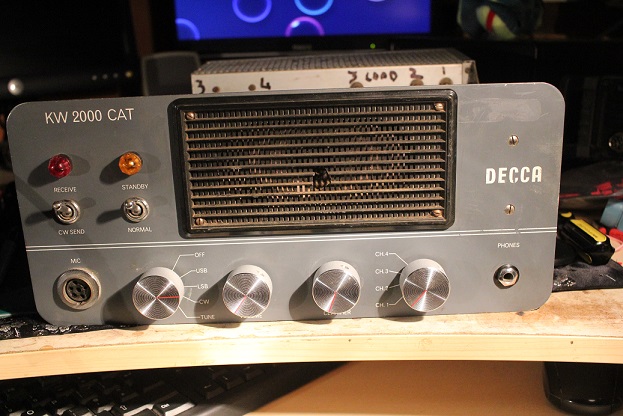
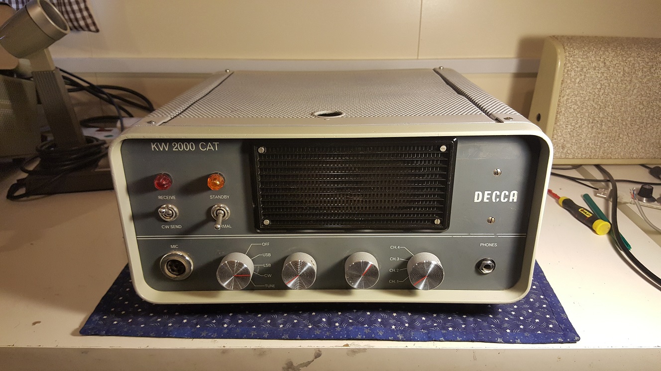
KW / DECCA made a few versions of this commercial radio; the early ones (before DECCA bought KW) were based on the valve KW2000 and were designated the KW2000C/CA (on the left in the pictures above). After DECCA became involved in the mid 70s they identified a big market for UK Embassy and commercial HF communications and the radio was completely redesigned with Plessey 600 series RF and IF ICs - using a 12BY7 driver and 2 x 6146s in the PA - so a hybrid. It was renamed the KW2000CAT and by all accounts was quite a popular item in the KW/DECCA range. There are NO plugs and sockets on any of the PC boards, so although its pretty rugged its a nightmare if you need to change even one component. The IF board has every wire cut so that the board could be removed and the filters taken out. This is a lucky break as its possible to match up the wire colours and see where they all went - so there is a chance that the board could be re-installed
The 'CAT' version is shown on the right in the pics above (although mine did not look this good !). The handbook says 4 channels in the range 2 -12 MHz, and they must have been made to order depending on where those 4 channels were required. I dont have the PSU either but I could rustle up all the required voltages. The solid state parts just require 12V.
FEB 2018 UPDATE 1 - Proper 1.4 MHz USB / LSB filters fitted (even if different bandwidths !), cut wires all remade, cheap knobs ..awaiting 1.4 MHz carrier crystal then try it with DDS into the crystal sockets on RX !

FEB 2018 UPDATE 2
One of my mates came up with 1.4MHz carrier crystal and the damn thing works on RX. For 80m I used one of my DDS units to run from 4.9 - 5.2 MHz and inserted the LO signal into the channel crystal oscillator. Without a PC board layout it was a bit trial and error, but in the end I tapped onto the FET that would have been the crystal oscillator. The CAT has 4 HF channel positions and I reasoned that the first one would probably be the lowest in its 2 - 12 MHz range. I was right and could peak the front end coils easily for 80m. 40m RX also worked best on position 3, and again I could peak the coils easily. SSB sounds quite good although my USB filter (used for LSB) is a bit wide at 2.75kHz. Now to try and get some TX SSB out of the driver stages !
FEB UPDATE 3
Using a Shure 444 I got very TX nice audio out of the predriver stage - listening to it on another receiver. Looks like a PA rebuild is in order..prob just for 80m. The £1 radio is a lot of fun.. Needs a front end attenutaor on RX as it can be a bit too lively on 80m !
FEB UPDATE 4
Decided to strip out all the remaining PA components and do a complete rebuild of the PA with proper plate and load caps rather than the original preset arrangment (means I can change frequency a bit!) . NOS 12BY7 and 6146B valves, new parasitic suppresors, new 80m tank coil
I had to make some custom metal brackets to use the variable caps I had to hand. Managed to repair and repaint the scruffy plastic speaker grille. I keep reminding myself this was just a junk chassis when I first got given it...now its become an obession to make a working 80m 100W SSB transceiver.
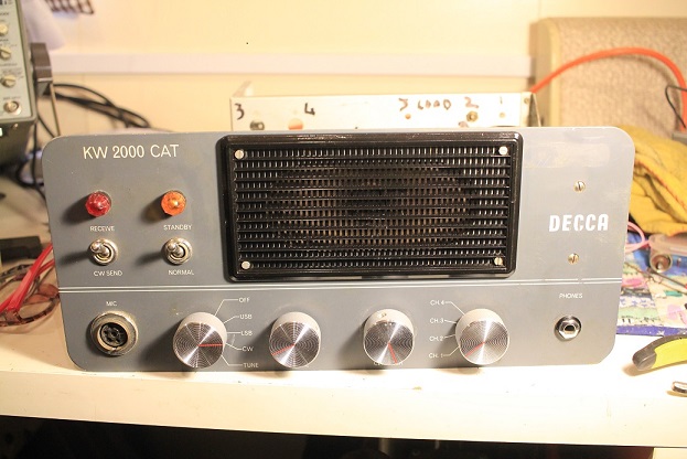
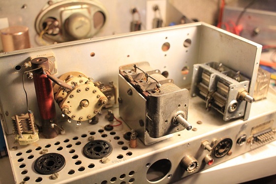
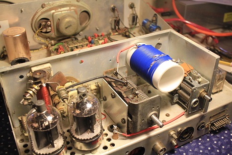
The pictures above show the PA layout. In its original state there were 4 switched PA Tune capacitors on the far right front. - the mounting holes are visible. Although these were present I thought the plate spacing was quite narrow and retuning across a band would be difficult as the caps were only screwdriver adjustable from inisde the radio. The PA Load capacitors were made up of large compression trimmers with fixed capacitors swtiched in on each of the 4 channels by the large ceramic PA switch wafers. Again adjustment would only have been possible inside the radio.
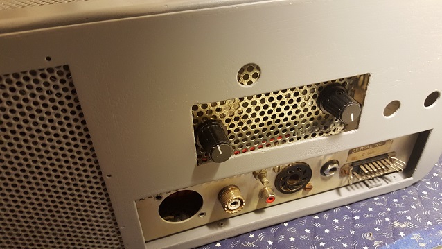
Although this was designed as a preset channel transceiver my DDS gives me a usable range of more than 50kHz on 80m and I opted for an industry standard PA arrangement that would give me some room for matching adjustment. The 2 X 6146s valves require a tank coil of around 10uH (for 80m). The PA load capacitance needs to be around 1100pf - I used 500pf variable and 800pf of fixed padders. The wide spaced PA tune capacitor is from a Heathkit HW100. Of course these two controls will stick out of the back of the case...but better than butchering the front panel
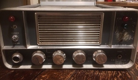
FEB UPDATE 5
The CAT IS ALIVE!. Running from 2 separate power supplies (LV and HV) and my DDS I was able to get 80W out on 80m and have plenty of contacts. Using a SHURE 444 I'm told it sounds just fine. Briefly caught out by a duff 12BY7 from my junk box..but another one restored good OP power.
The home brew 2 X 6146B PA works a treat and I am amazed that this radio is back from the grave. I am sure it would have been thrown away if Andy G4ADM hadn't bought it for £1 and given it to me. My ONLY purchase for this radio was the nice aluminium knobs which cost £1 at the Canvey Radio Rally..everything else has either been donated to me or come from my parts stock
https://www.youtube.com/watch?v=nYHdMNQQ5hc
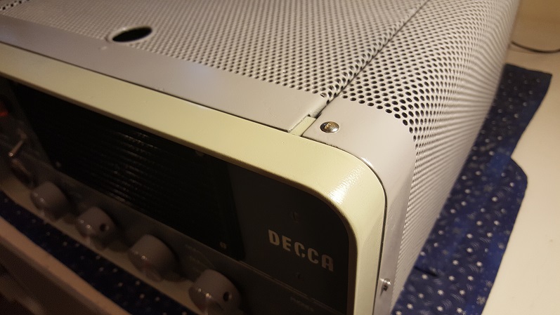
Gifted a suitable KW 'G Line case' that needed some work and painting - but I had to break one of my golden rules and cut into it. I just had to have proper adjustable PA 'tune' and 'load' on this radio, not preset (at it would have been) and definately NOT by drilling into the front panel (that would be a step to far). The only alternative was to cut into the rear of the case for access to my new PA variable capacitors - I tried to make it look as professional as I could. Pretty much a completed project...may add 60m /40m switched on CH2 and CH3 at a later date
Connect with me today
Call me on 44 (0)7970 190437